- Super-capacitors and regulators for consistent lighting.
- 5 LEDs to insure uniform lighting.
- Connections for up to 8 marker lights (4 red and 4 green). The lights are in groups of 4 which can be selected by a magnetic wand.
- Cabin lights adjustable from dim to bright.
- Maximum track voltage is 16 Volts.
- Magnetic light on/off control.
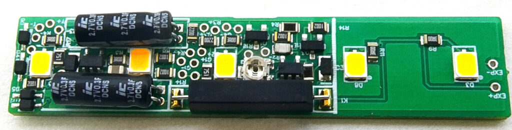
Super-capacitors and regulators provide constant lighting. Each board has 5 LEDs to insure uniform lighting (see photos). The LEDs are designed to simulate incandescent style lighting. Instructions and most parts for installation in cars without pickups are included. Metal wheels are required and must be obtained separately. You can use supplied parts to make your own pickups. Adjustable from dim to bright. When adjusted for normal light levels the car will remain lit at constant brightness for up to a 15 seconds after power is removed. Size: 2.45″(62 mm) x 0.51”(13 mm) x 0.23”(6 mm). Can be shortened as much as 0.83″ (21 mm) to a length of 1.61″ (42 mm).. Click here to download the product pamphlet and description. See below for installation information. Price is $39.95.
Reviews:
Add your review here:
* U.S.A. Shipping is $5, Canada 9.95 USD, otherwise 14.95 USD
Installation Information:
Magnet wire is used to connect the light board to the wheel contacts. The first step is to drill the holes in the chassis for the passage of this wire.
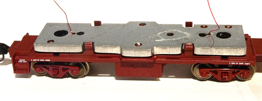
Contacts are made from the supplied phosphor bronze wire. Wrap the wire around each axle at least two times. If the wheel does not rotate freely then pull the wire to loosen the wrap.
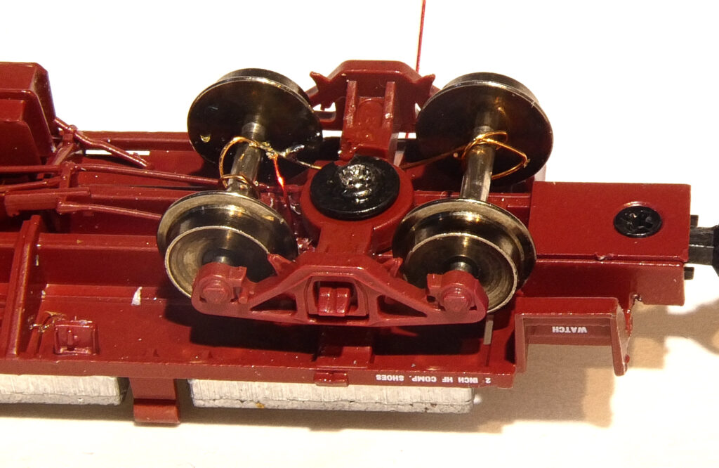
Tin the end of the supplied magnet wire by placing a bead of solder on the iron’s tip and holding the magnet wire in the solder bead until the insulation burns off and the wire is tinned. Insert the magnet wire into the drilled out holes.
Solder the magnet wire to the copper phosphor bronze contact wire at a convenient place between the wrap and the plastic bolster. Be careful not to melt the bolster. Repeat for the other truck. Position the insulated wheels of the second truck on the opposite side of the car so that you have a pickup on each rail.
Solder the other end of the magnet wire to the T+ and T- points on the light board. Do not remove the soldering iron until the magnet wire insulation is fully burned off at the point of contact.
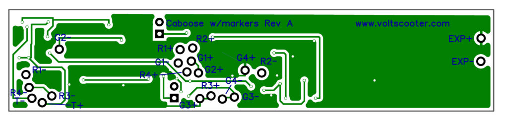
Solder the leads from your red and green marker LED lights to the R & G pads to on the light board. Resistors are already installed on the light board so external resistors are not required. The first red LED should be connect to the R1+ and R1- connections on the circuit board. There are two sets of LED marker lights. Only one set is on at a times. R1, R2, G1 & G2 are in the first set and R3, R4, G3 & G4 are in the second set. Normally the R LEDs are visible from the rear of the train and the G LEDs are visible from the front of the train.
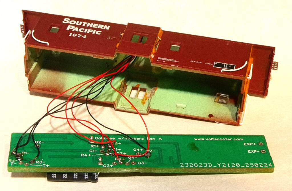
In this example I only connected red forward and red reverse LEDs.
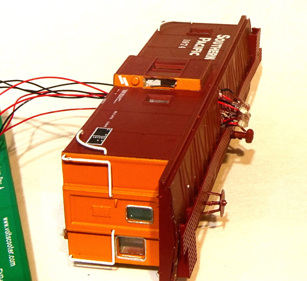
Connect track power or 12 Volts DC to the trucks and test the operation of the light board. Install the light board into your car. Adjust the light with the
supplied screwdriver to the desired brightness of the cabin lights. Caboose lights are normally very dim so as not to interfere with night vision by the crew.